Major
assemblies:
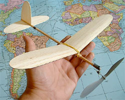
- First, download the plan. The
model has a 12 inch (30.5cm) wingspan, so when you print the plan
be sure the wing half is exactly 6 inches (15.25cm) long.
- Cut the motor stick (fuselage) from stiff 1/8" x 3/16"
(3mm x 4.5mm) stiff balsa stock. These dimensions can vary slightly,
but be sure the stick is stiff (and preferably light).
- 2 wing halves, the stabilizer, and the rudder are cut from very
light sheet balsa, 1/32" to 1/20" thick (0.8 to 1.25mm).
- Wing ribs are cut from 1/16" (1.5mm) sheet balsa.
- Lightly mark rib locations on both wing halves, and glue the
center portion of each rib (peak of airfoil) to it's proper location
on each wing (approx. midway between leading and trailing edges).
After glue is dry, apply glue to remaining lengths of ribs and
flip wing assemblies over. Place wings on a flat surface and use
weights along leading and trailing edges to make the balsa sheet
conform to the rib profiles while the glue dries.
- (Optional step) The wing can be made damage-resistant by gluing
thread along the leading edge, from wing roots to wing tips.
- Both wing halves must fit together with 1.5" (3.8cm) dihedral
under each wing tip. Sand the top section of each wing half where
they meet (root ribs) until a good fit is achieved, and glue halves
together with proper dihedral.
- Cut a square notch out of the rear of the motor stick to accomodate
the stabilizer, as shown on plan. Make the cut straight &
square, and approx. half the height of motor stick. Length of
cut should be longer than width of stab by about 1/4" (6.5mm).
Next, cut a piece from 1/16" (1.5mm) sheet the length of
the motor stick notch, and the width of the motor stick. Assemble
this piece and some small pieces of 1/16" scrap onto the
motor stick to create a slot for the stab to slide through. Position
the stab in the notch during assembly to ensure it sits squarely
in the slot while glue dries.
- The wing mount pieces are cut from 1/16" (1.5mm) balsa
sheet and assembled as shown on plan. The mount should fit snugly
over the motor stick, and must be able to slide freely along the
length of the motor stick.
- At this point, 2 to 3 coats of Nitrate dope should be applied
to all balsa parts. Hold stab and rudder flat while dope dries.
Dope only one half of the wing at a time, and weight it down on
a flat surface as it dries, with a shim under the trailing dge
to create washout. The shim should be approx. 1/16" (1.5mm)
thick, placed under the trailing edge approx 1/4" (6.5mm)
outboard of the outer rib.
- Sand very lightly between coats of dope, and be sure to brace
parts as described above while drying each time.
- Slide stab into stab slot, and glue rudder to motor stick as
shown on plan. Ensure that rudder is square with stab while drying.
- Assemble wing mount to motor stick (do not glue). Glue wing
to wing mount with a 1/16" (1.5mm) shim underneath the leading
edge. Ensure wing is square with rudder and stab, and also square
in the top-view, before glue dries. When dry, remove wing/mount
assembly from motor stick.
- The thrust bearing mount is made from aluminum-angle, approximately
1/16" x 1/2" x 3/4" (1.5mm x 1.3cm x 2cm). Cut
off a section of aluminum-angle about the width of the motor stick.
Next, cut a section of thin aluminum from a beer or soda can,
and wrap it tightly around the long section of the aluminum angle
piece. It should wrap only one time around, and overlap itself
about 1/8" (3mm), creating a "socket" that the
angle can slide in and out of. Bind the thin aluminum wrap with
several truns of thread, and lock the thread with a thin coat
of superglue (CyA). Be careful that you do not glue the aluminum
angle to the thin aluminum.
- The socket (with aluminum angle still inserted) should be glued
to the motor stick as shown on the plan. When glue is dry, lash
the socket to the motor stick with thread and glue (Cya) to create
a solid attachment. Once glue is dry, slide the angle out of its
socket and back in a few times to check the fit.
- The short leg of the aluminum angle should be filed so the that
the end mates to the round profile of a Peck plastic thrust bearing
(as shown in sketch on plan). Lash the plastic bearing to the
angle with 10 or 15 turns of thread, and harden the joint with
superglue (Cya).
- Bend the rear motor hook out of .025" (0.6mm) music wire
as shown on plan, and lash to motor stick with thread and Cya
glue.
Final assembly:
- Small areas of bright paint or tissue are recommended to make
your model easier to find.
- A 4.5" grey plastic Peck prop works well for the World
Tour Flyer. Scrape plastic from the front and/or back
of the prop to make it balance. For best performance, a great
deal more plastic can be scraped away to lighten the weight.
- Use pre-formed motor hooks, or bend your own to attach the prop
to the thrust bearing. Ensure that the free-wheel mechanism functions
properly.
- Attach the wing to the motor stick using a single small rubber
band.
- Slide the thrust bearing assembly into its socket.
- Slide the stabilizer into its slot.
- Tie a loop of 3/32" (2.5mm) or 1/8" (3.2mm) rubber,
about 8" (20cm) long. Stretch & lube the motor, and attach
to front and rear motor hooks.
Flight Trimming:
- Slide the wing to a position on the motor stick where the CG
(center of gravity) is about where the airfoil peaks (1/3 to 1/2
of the way back from the leading edge). Mark the motor stick and
the wing mount so you can easily find this position again.
- Hand-wind 25 to 50 turns into the rubber to begin flight tests.
- Adjust wing position to cure problems in the glide.
- Thrust adjustments are made by bending the aluminum angle portion
of the thrust bearing assembly. Use two pairs of pliers for this
operation.
- If flight surfaces need to be warped (or if warps must be removed),
hold the warp in position while brushing dope thinner over the
balsa. Continue holding until dry. Steam also works well for this.
|
|